About
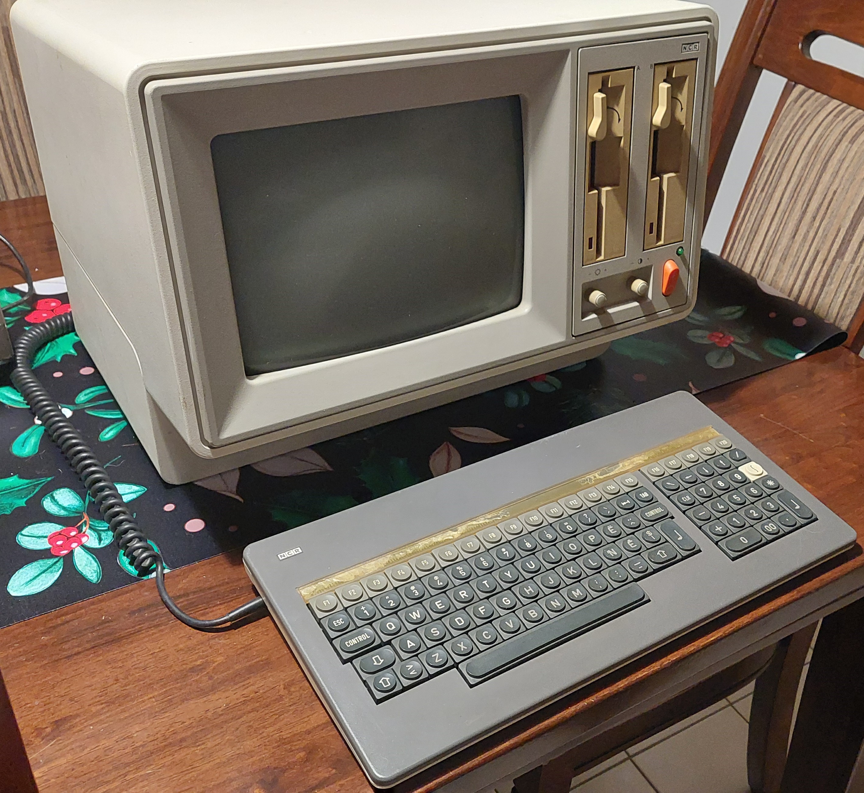
I received this computer from a very kind person advertising floppy disks on our neighbourhood WhatsApp group in December 2024. When I inquired, I was surprised to learn that they also had a few other items, one of which was this NCR DMV! They received it after cleaning out a garage for someone else. Unfortunately all the floppies were blank so I had no software and the machine showed no sign of life when I tried to turn it on.
I managed to repair the machine, write software to floppy disks and boot it.
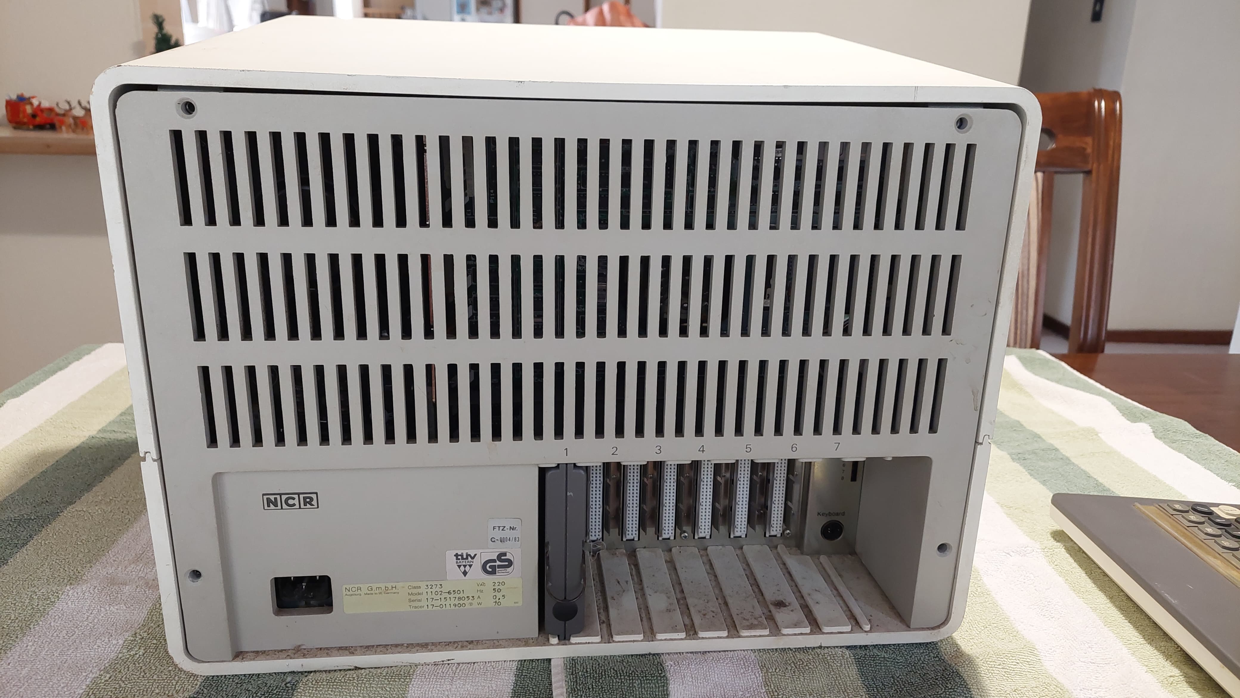
Model number
- Model: 1102-6501
- Serial: 17-15178053
- Tracer: 17-011900
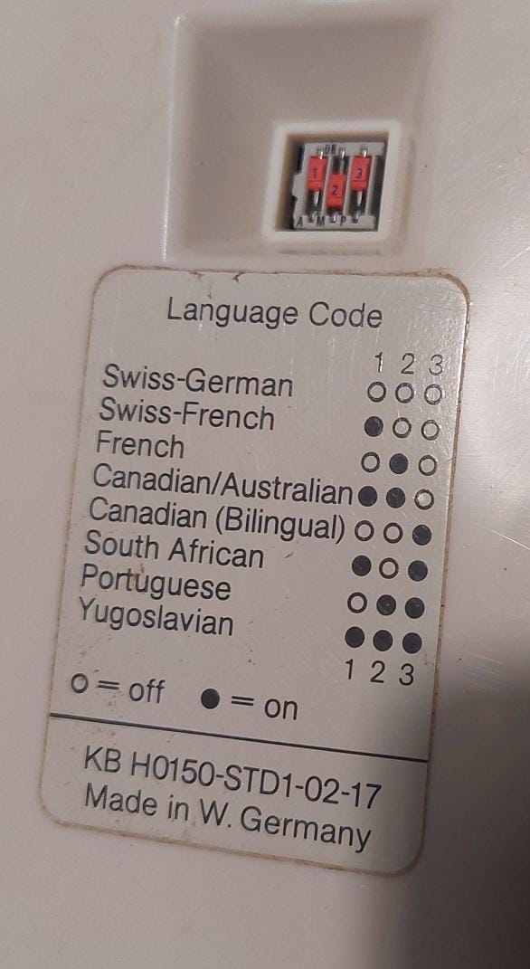
- Keyboard: KB H0150-STD1-02-17
Adverts

Repair
When I tried to power it on, it had no life, not even the power LED came on. This indicated a problem with the power supply.
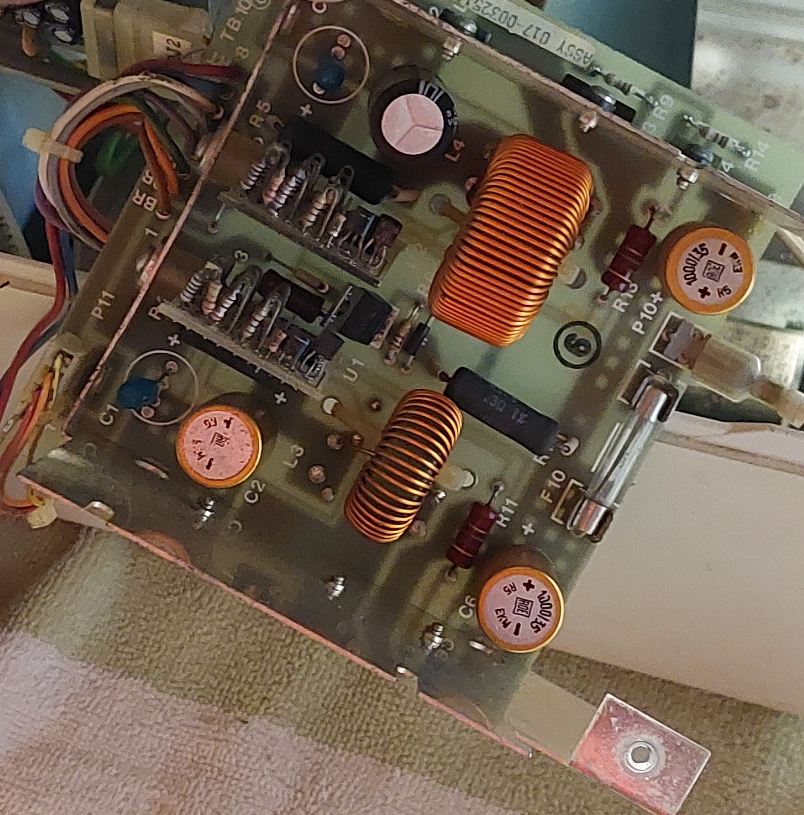
Power Supply
After opening up the machine, a visual inspection of the power supply immediately revealed that the capacitors used on the rectification board were the culprits. Removing the board showed the capacitor leaking created a short across the tracks.
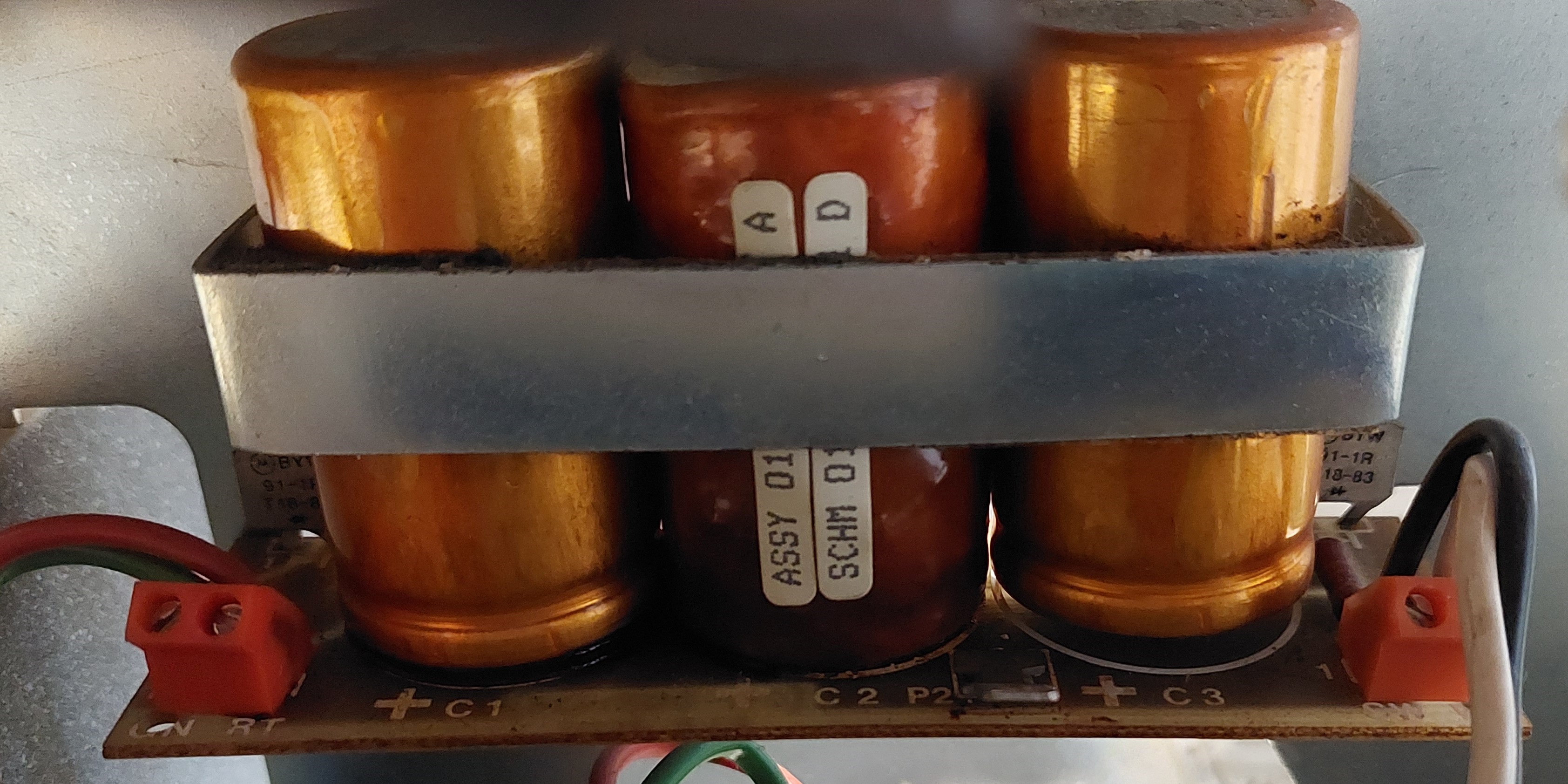
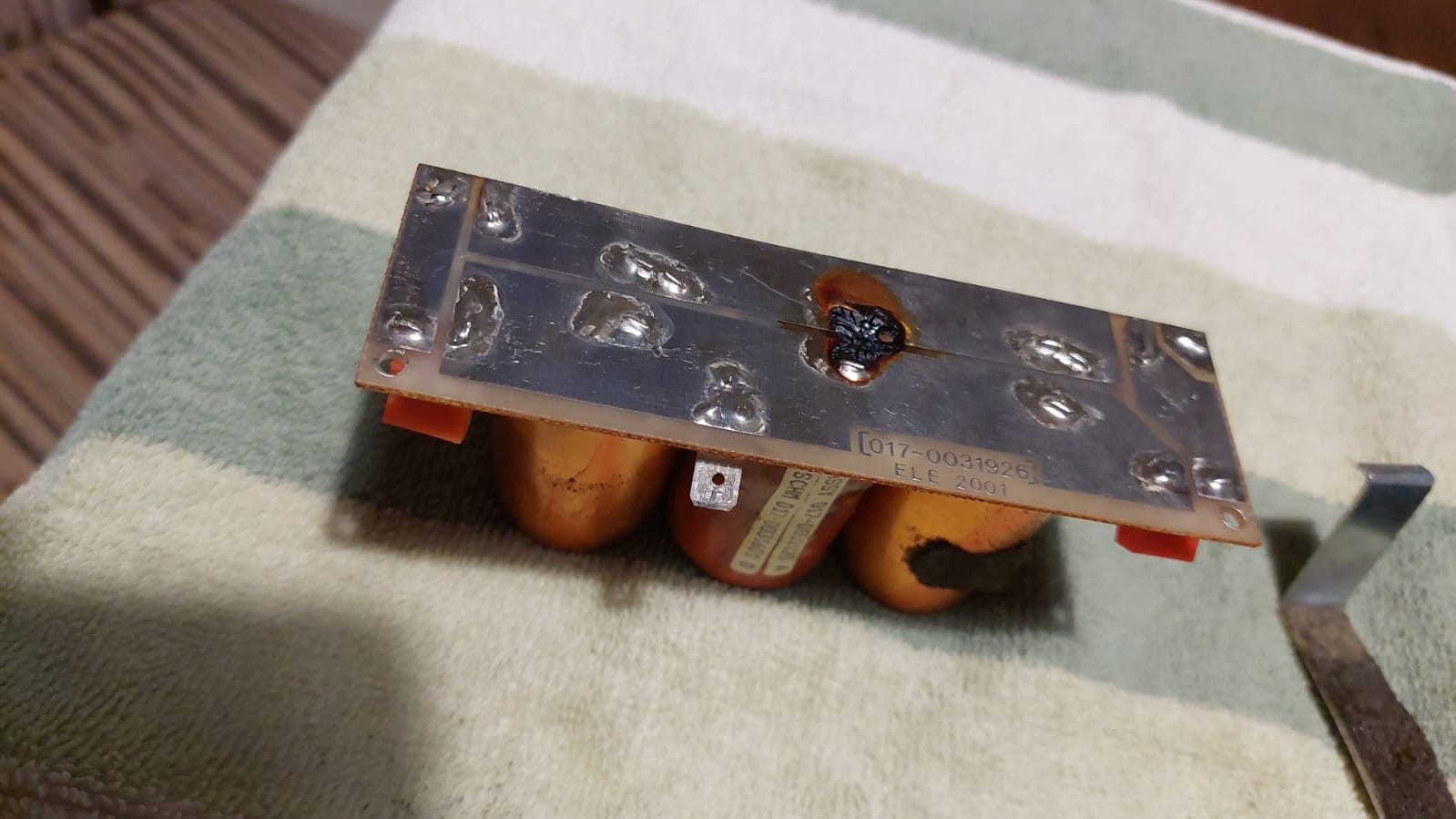
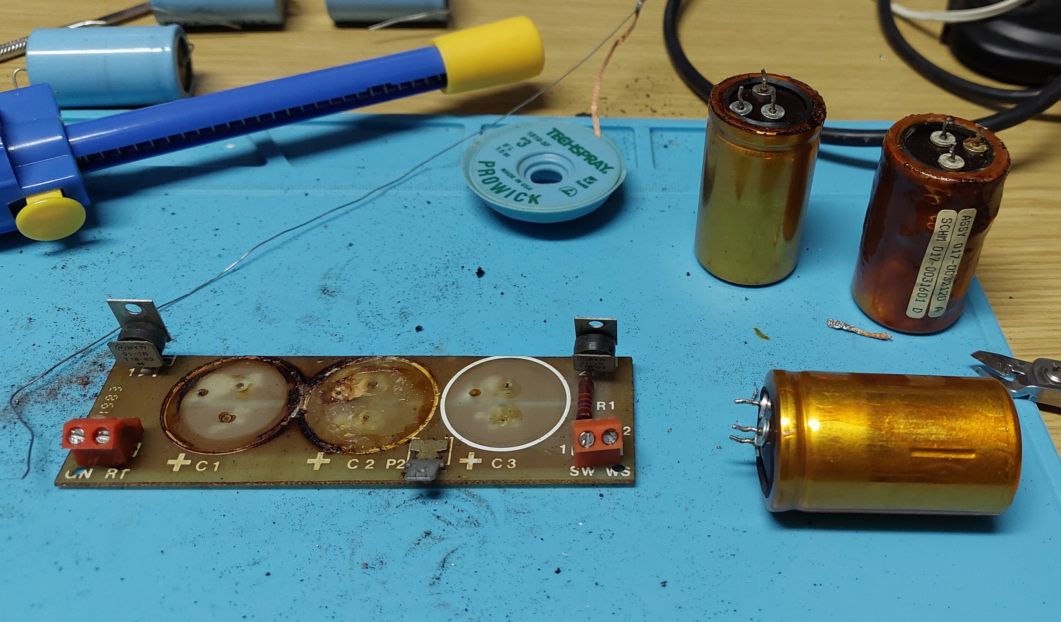
I cleaned the board and replaced the capacitors. The foam that held the capacitors in place was perished, so I replaced that with a slightly thicker piece of foam - the replacement capacitors were smaller than the original and they were used to clamp the board to the chassis. The main fuse was also blown and had to be replaced.
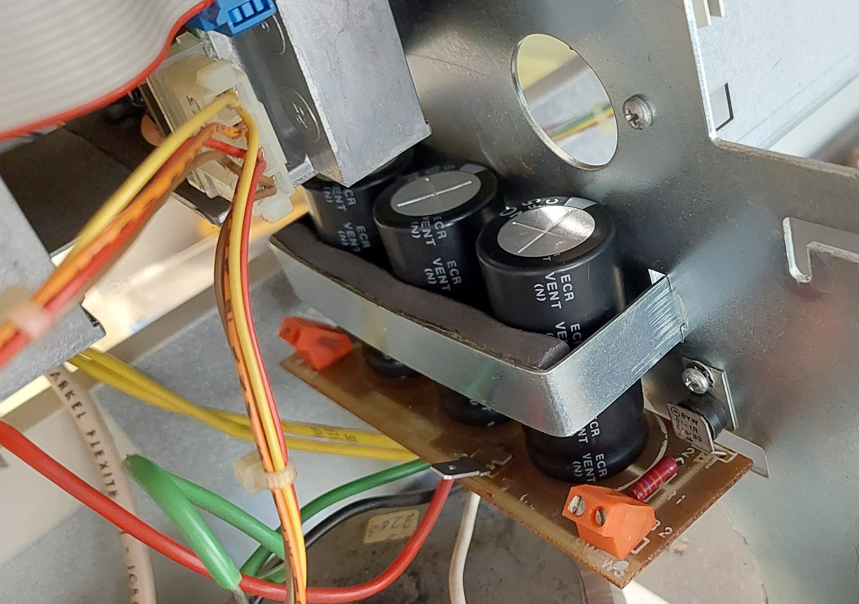
After this, voltages (12V and 5V) tested fine, and I connected the PSU to the mainboard. The power LED came on and the CRT powered on but did not display anything.
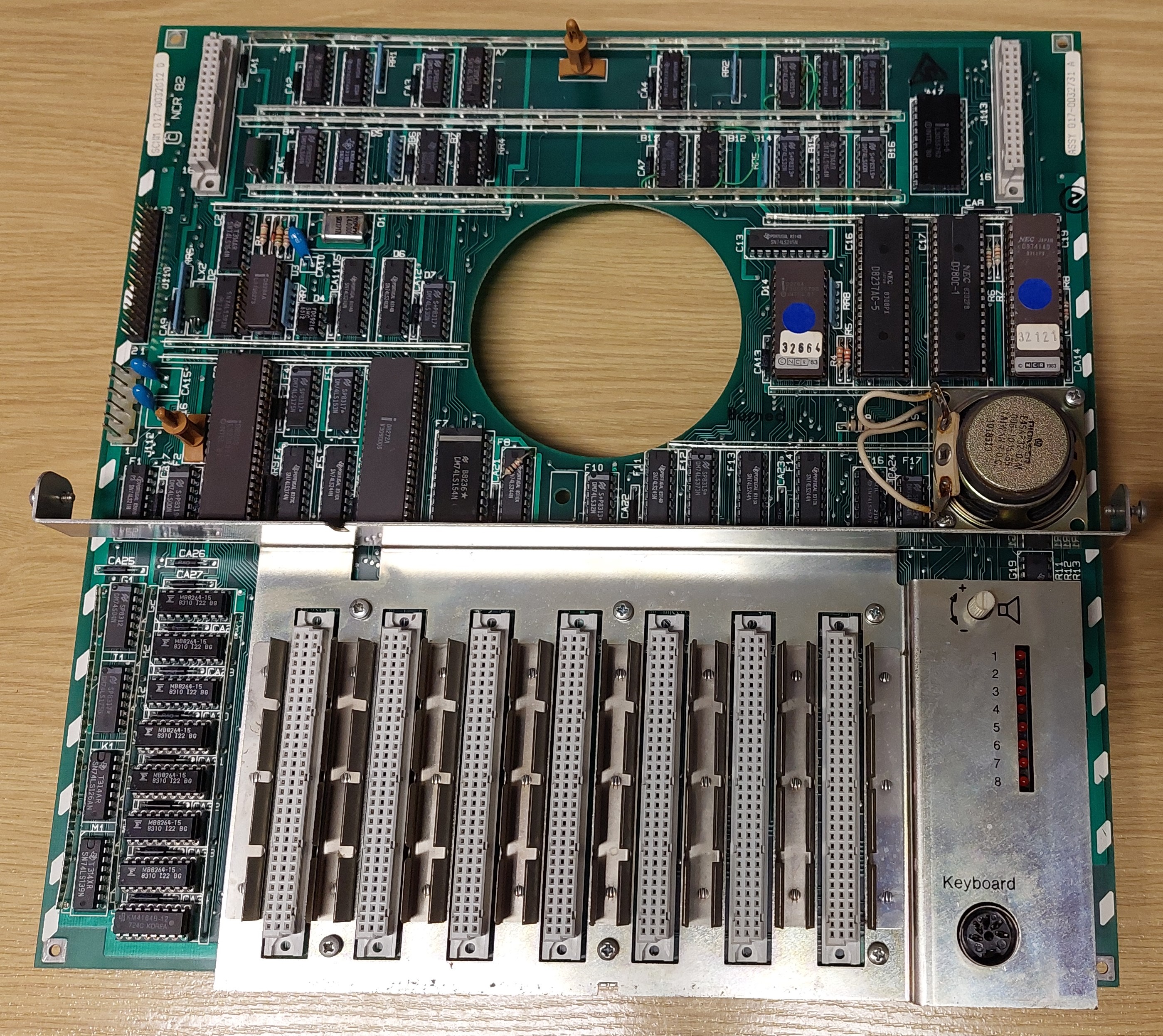
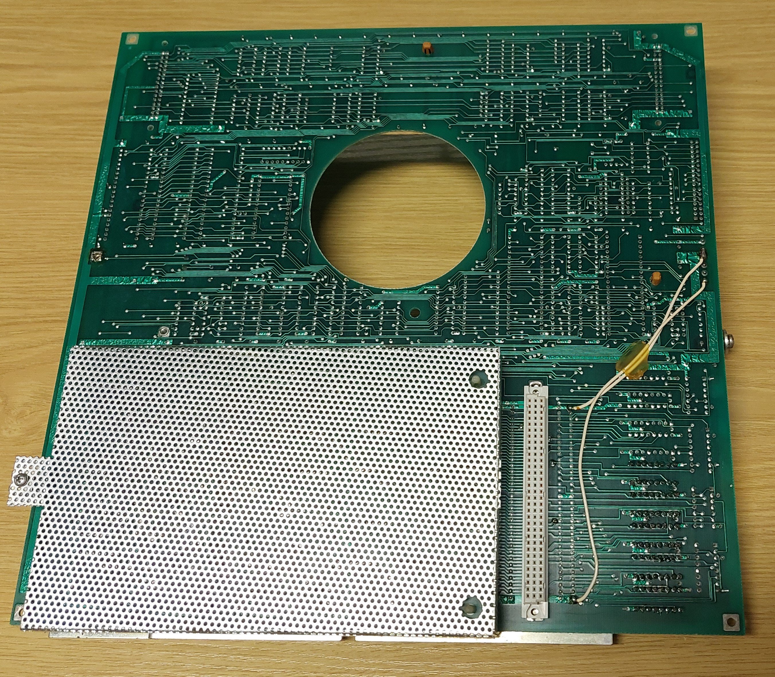
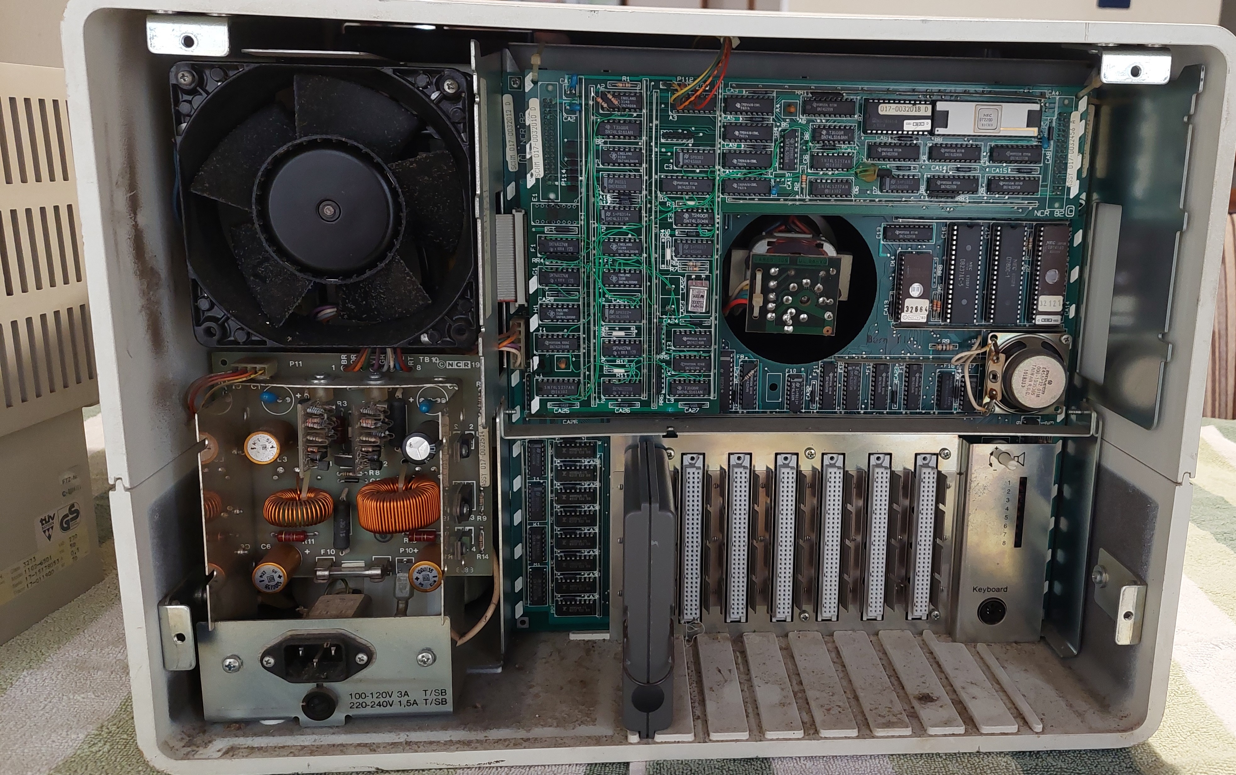
Main Board
The machine has a row of 8 diagnostic LEDs at the back
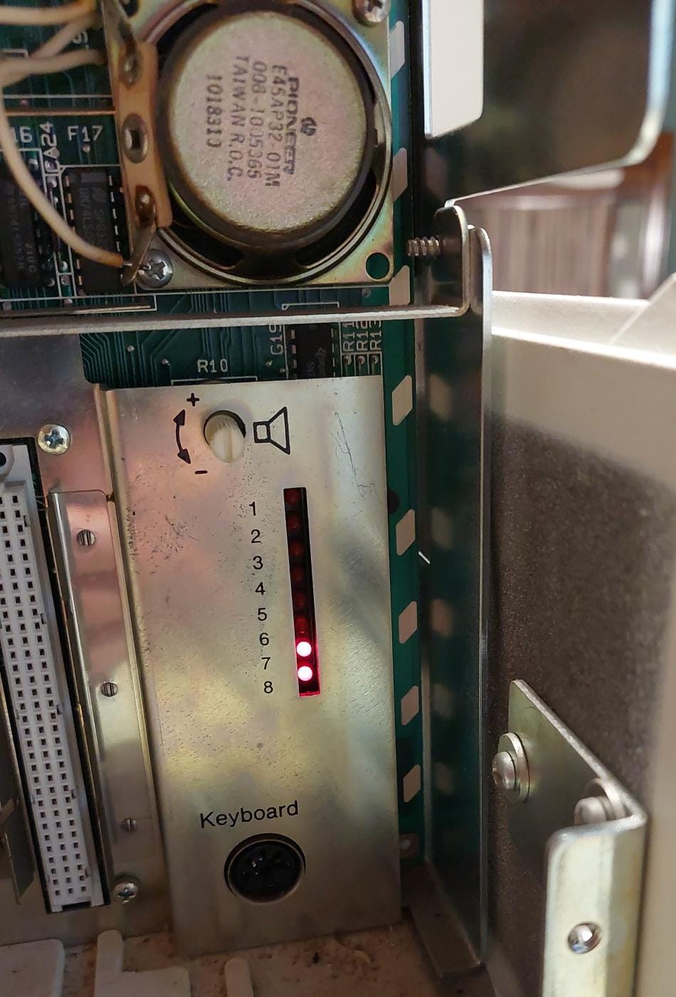
According to the documentation, this is the Level Zero Diagnostic panel
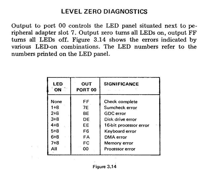
LED 7 and 8 indicates a memory error, so I started there.
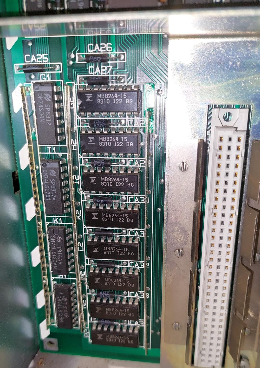
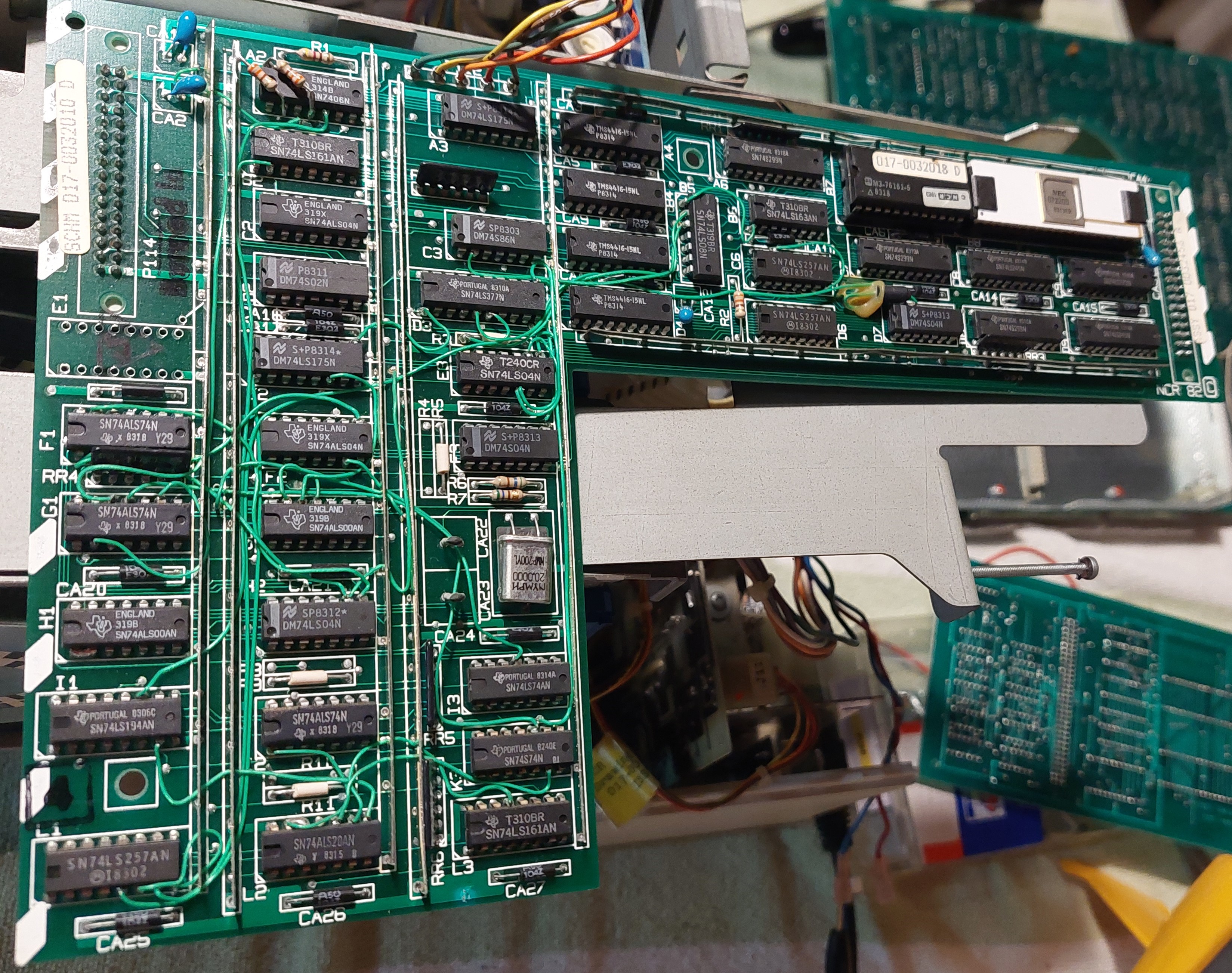
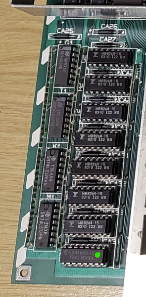
Unfortunately none of the RAM IC's are socketed, which makes testing them more difficult.
Just out of interest I compared the data line for each of the IC's on my scope before repair.
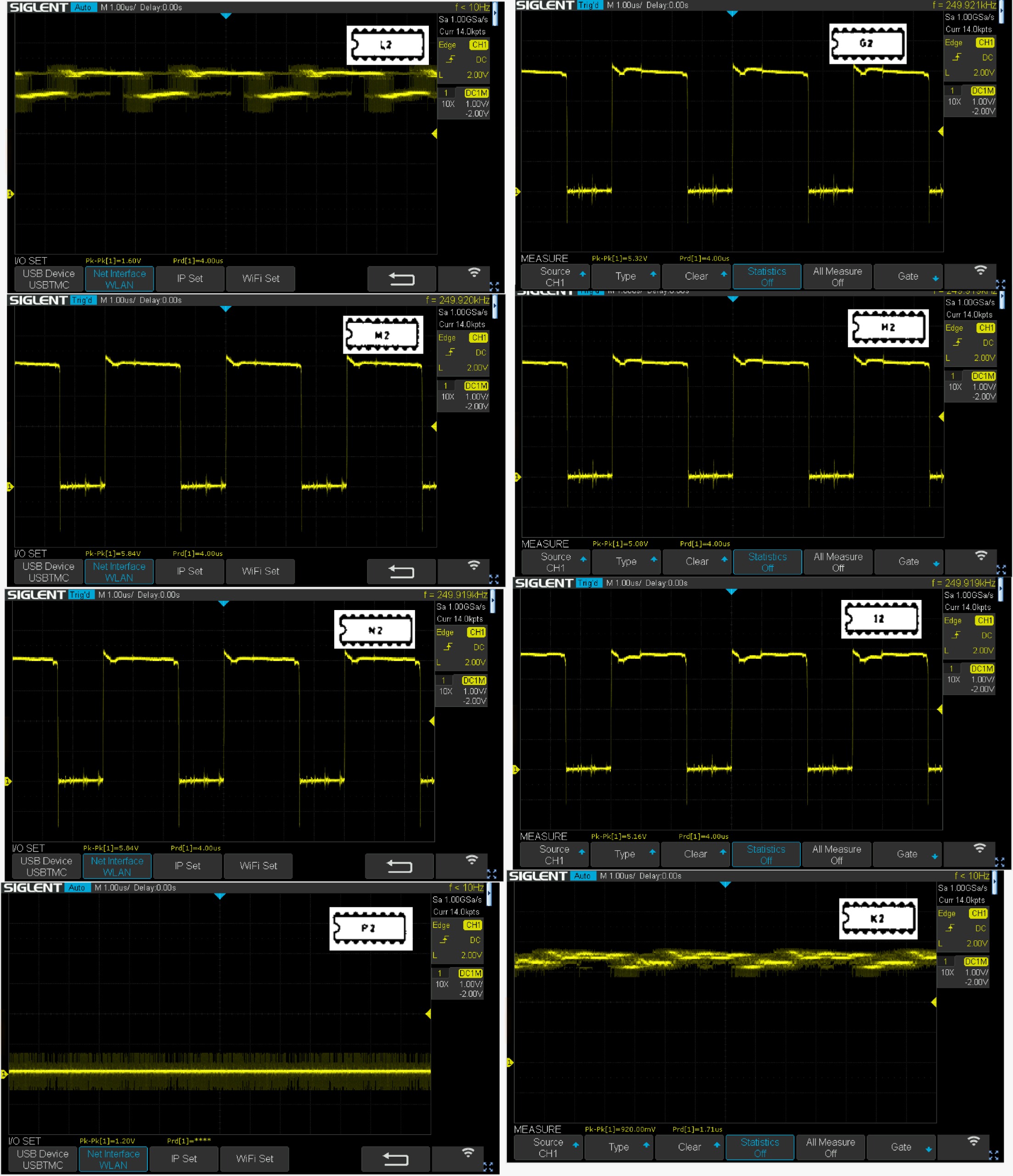
But to test them properly I needed to desolder them and test them individually.
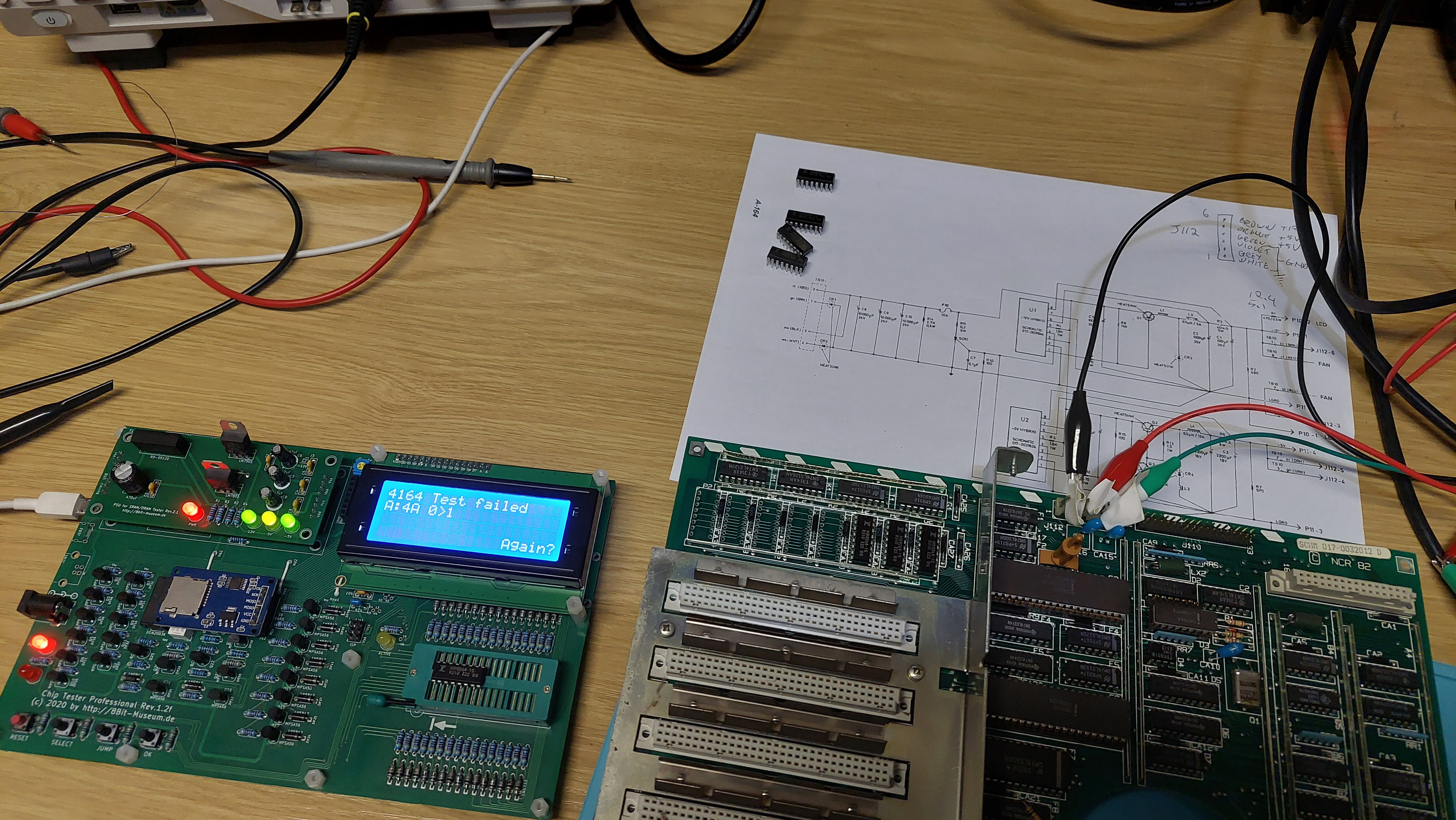
One of the RAM IC's were faulty, which I replaced (with sockets). After this this the machine passed the checks.
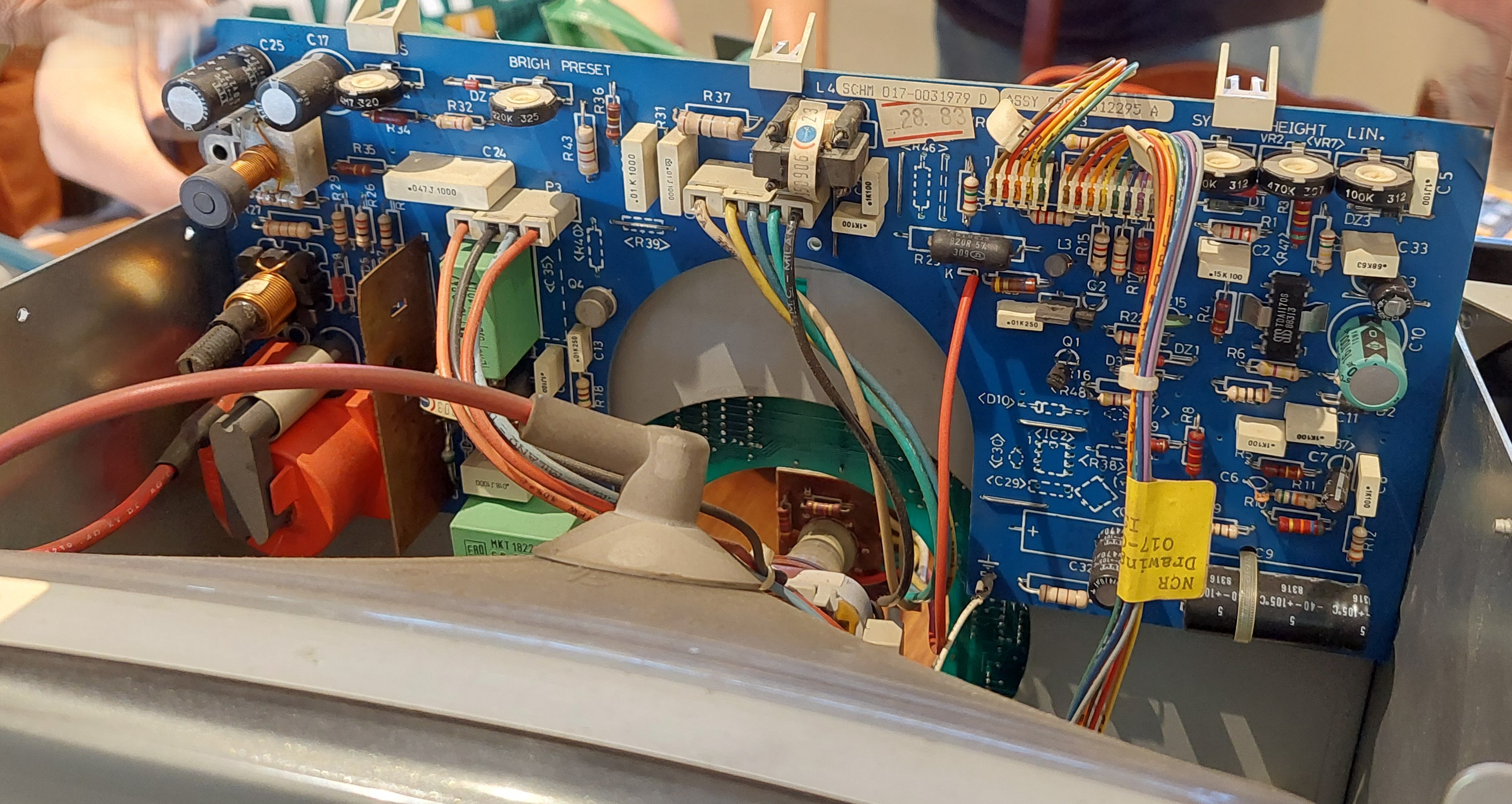
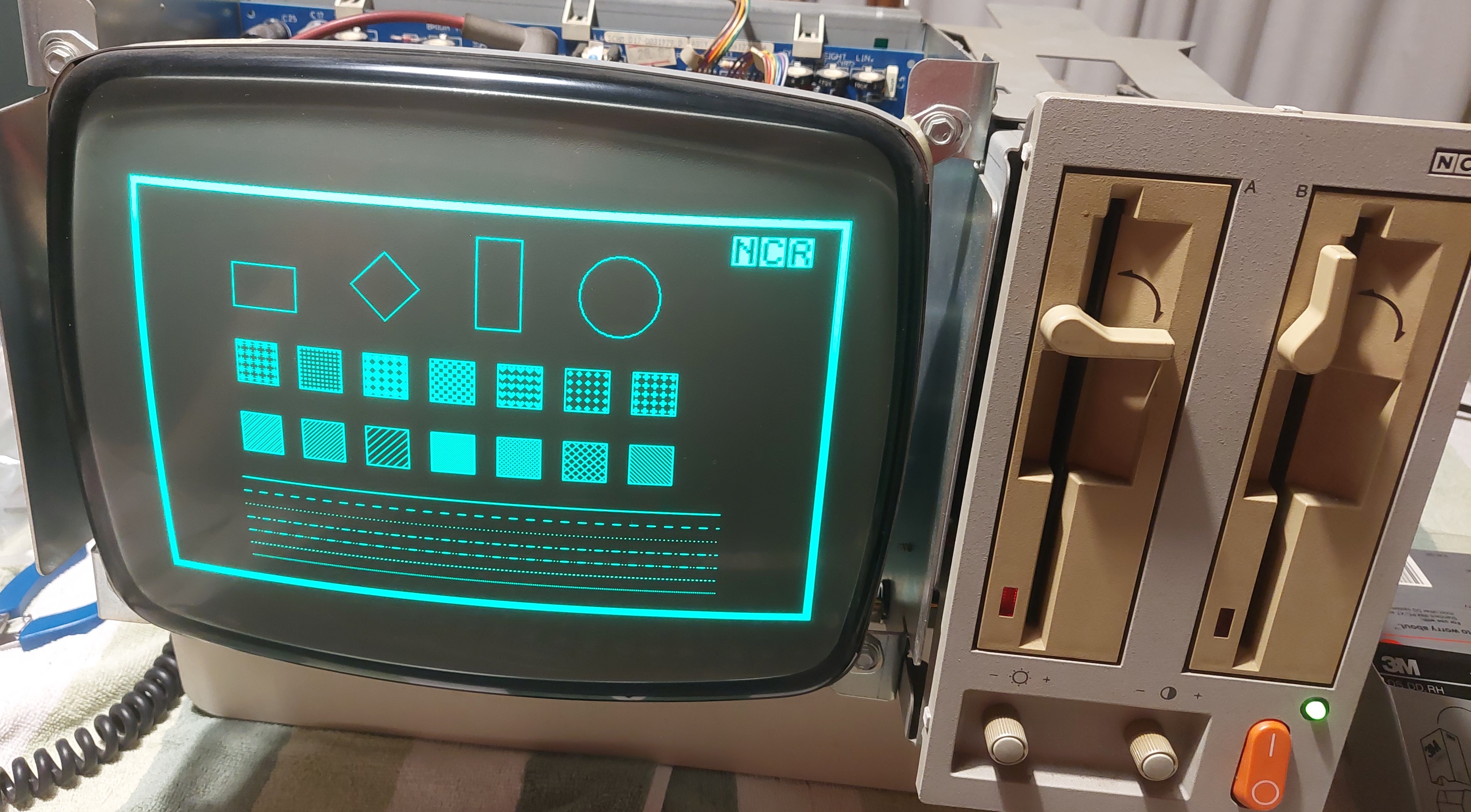
CRT
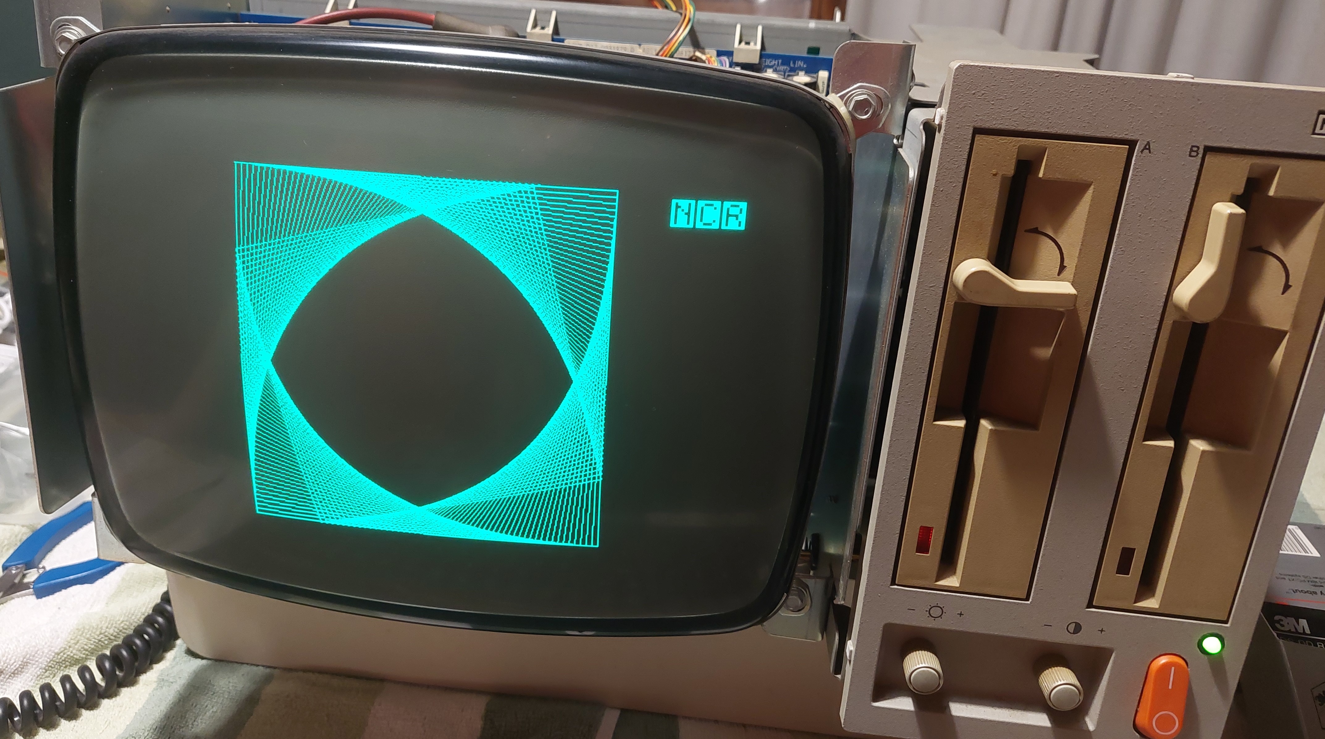
After running for a while, the vertical size started jumping, and eventually settled with a very squashed display, as can be seen in some of the screenshots of the various operating systems booting further down this page. Adjusting the V HEIGHT pot on the CRT board had no effect. After removing and testing a few components around this circuit, capacitor C3 tested as a short.

Replacing C3 resolved the problem with the shrunken vertical height.
Software
Making Floppies
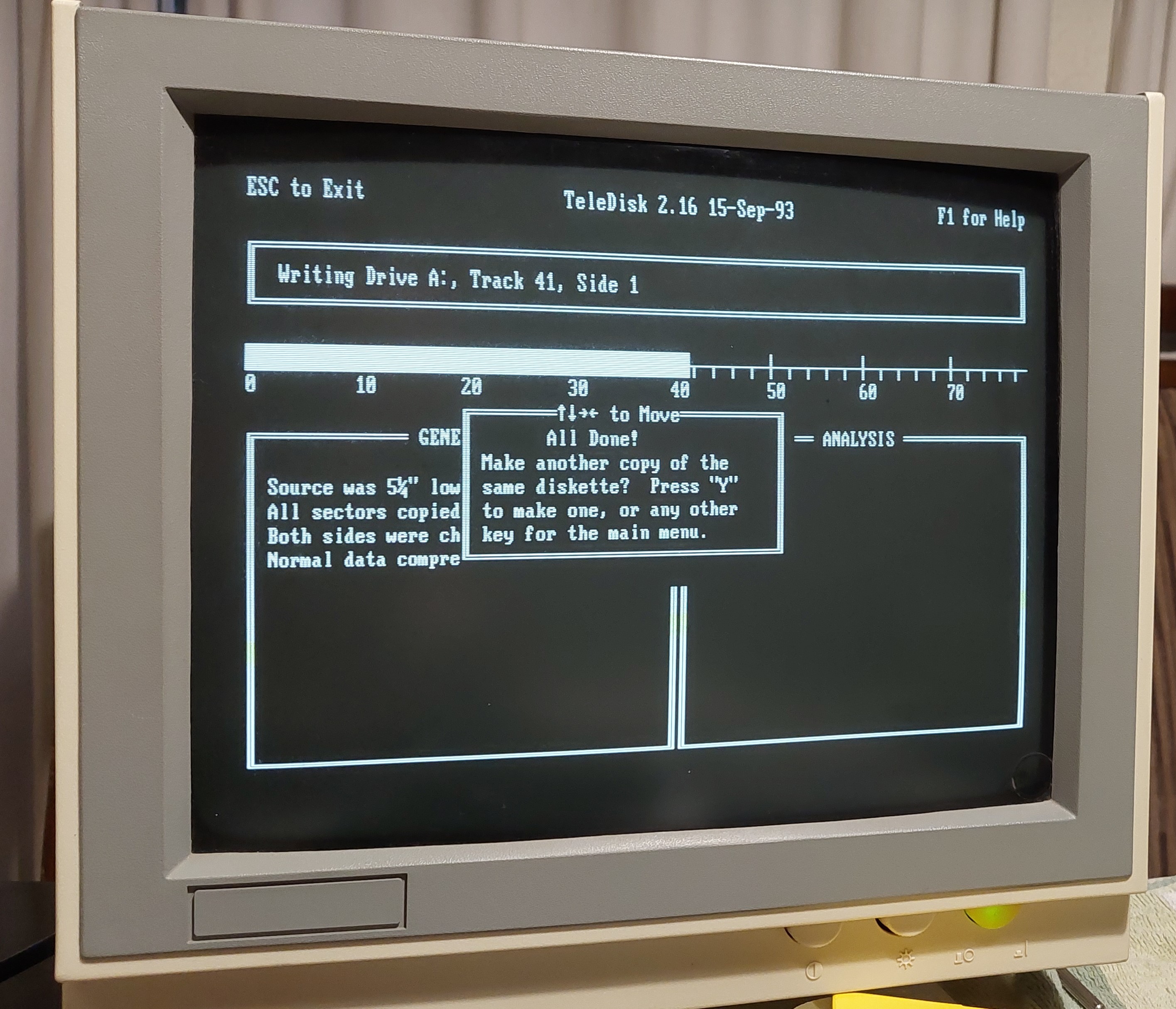
I found software online for the DMV, but only in Teledisk format. This software runs in DOS on an IBM PC Compatible, so I used a 286 machine with a 360K floppy drive to write the Teledisk images to a floppy.
- Teledisk 2.16 (DOS exe) 💾 teled216.zip
CP/M
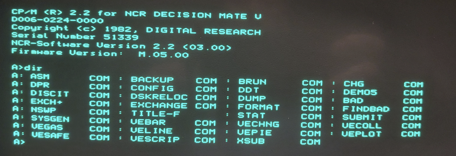
- CP/M 2.2 running on Z80 processor: 💾 580_sys.td0
CP/M86
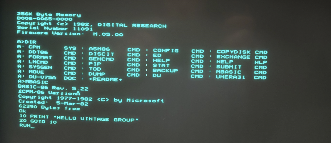
- CP/M86 running on 8088 processor: 💾 586sysmb.td0
MS-DOS
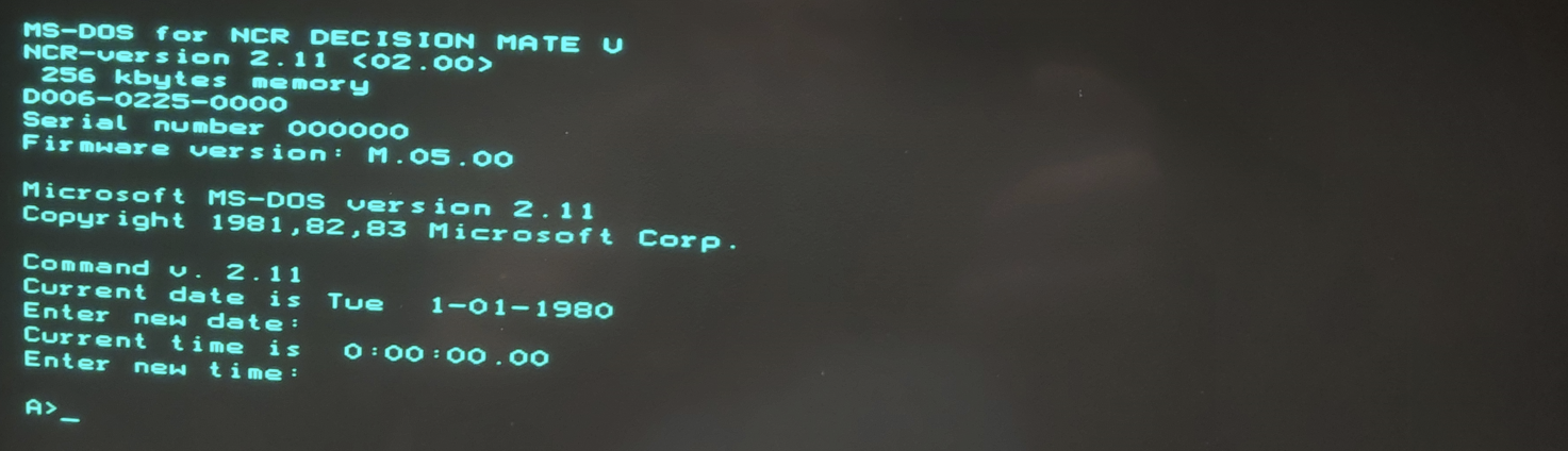
- MS-DOS running on 8088 processor: 💾 5dos211.td0
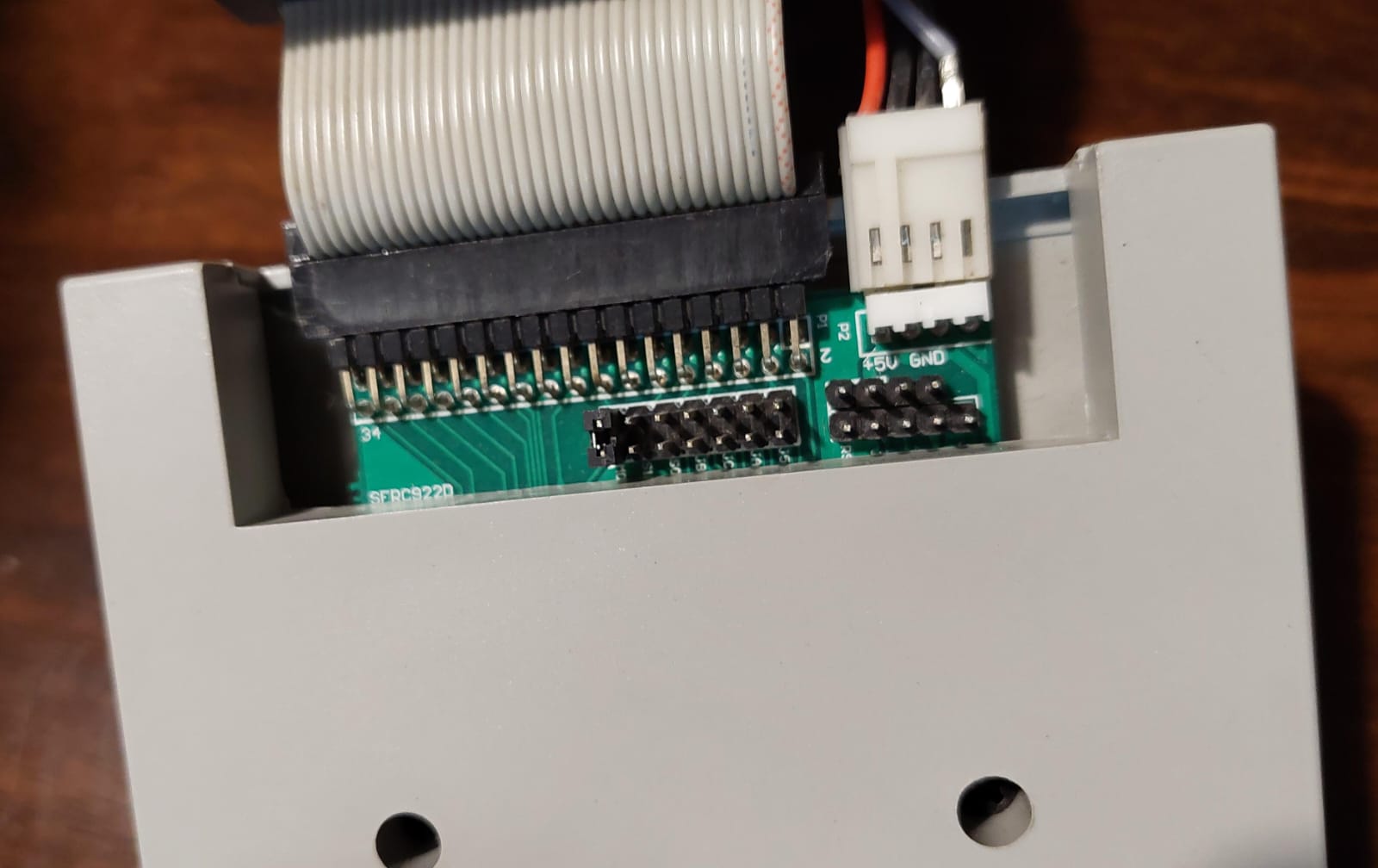
Floppy Drive Emulation
Emulation of the floppy drive with a Gotek running FlashFloppy worked, after converting the Teledisk images to HFE format. Which both HxC and FlashFloppy will read.
Converting floppy images
Use HxCFloppyEmulator software (I used v2.16.10.1) to convert the images from Teledisk to HFE
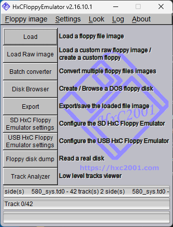
- Click on Load to load a .td0 image file
- Click on Export and choose "HFE file (SDCard HxC Floppy Emulator file format) (*.hfe)
Gotek Cable and jumpers
Cable used was a straight through cable, with only the MO jumper connected.
FlashFloppy Configuration
## FF.CFG: Example FlashFloppy Configuration File
# Place in the root folder or FF/ subfolder of your USB drive.

## DRIVE EMULATION
# Floppy-drive interface mode
# shugart: P2=DSKCHG, P34=RDY
interface = shugart

# Host platform: Improves image-format detection for generic types such as IMG
# unspecified: Common default geometries (including IBM PC)
host = unspecified

# Pins 2 & 34 output (drive->host) manual configuration
# auto: Auto-configure from interface= setting
pin02 = auto
pin34 = auto

# Forcibly write-protect images, or respect the FAT read-only attribute?
# Values: yes | no
write-protect = no

# Filter glitches in the SIDE-select signal shorter than N microseconds
# Values: 0 <= N <= 255
side-select-glitch-filter = 0

# Rotational offset of data after a track change
# Values: instant | realtime
track-change = instant

# Index pulses suppressed when RDATA and WDATA inactive?
index-suppression = yes

# Milliseconds from head-step start to RDATA active.
# Values: 0 <= N <= 255
head-settle-ms = 12

# Milliseconds delay from motor-on to drive ready.
# Values: ignore | 0 <= N <= 1000
motor-delay = ignore

# What causes the disk-change (chg) signal to reset after disk insertion?
# step: Step command received
# pa14: CHGRST (pin 1 on old Sony drives), connected to PA14 (JTCK/SWCLK)
# delay-N: Automatically after N*0.5sec (0 <= N <= 15)
chgrst = step
Converted image example
- DMV CP/M System Disk (bootable): 💾 dmvcpm80.hfe
ROM Dumps
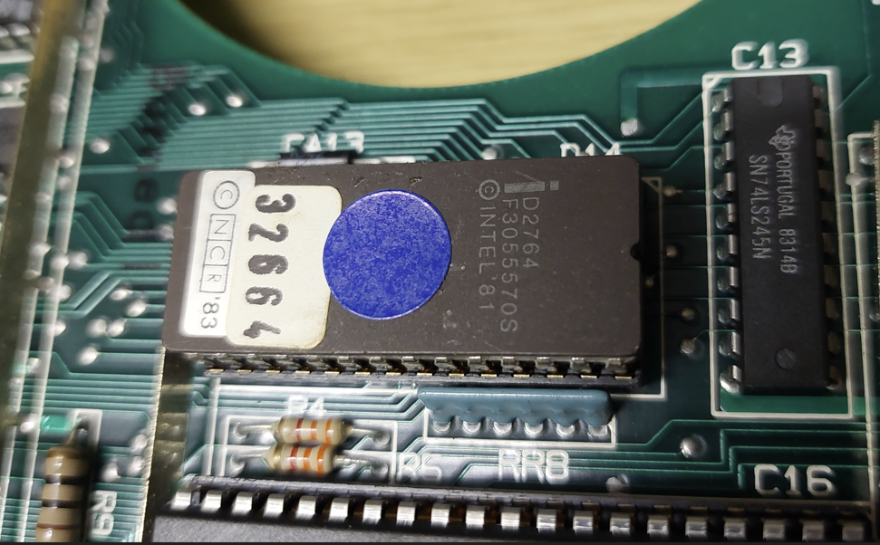
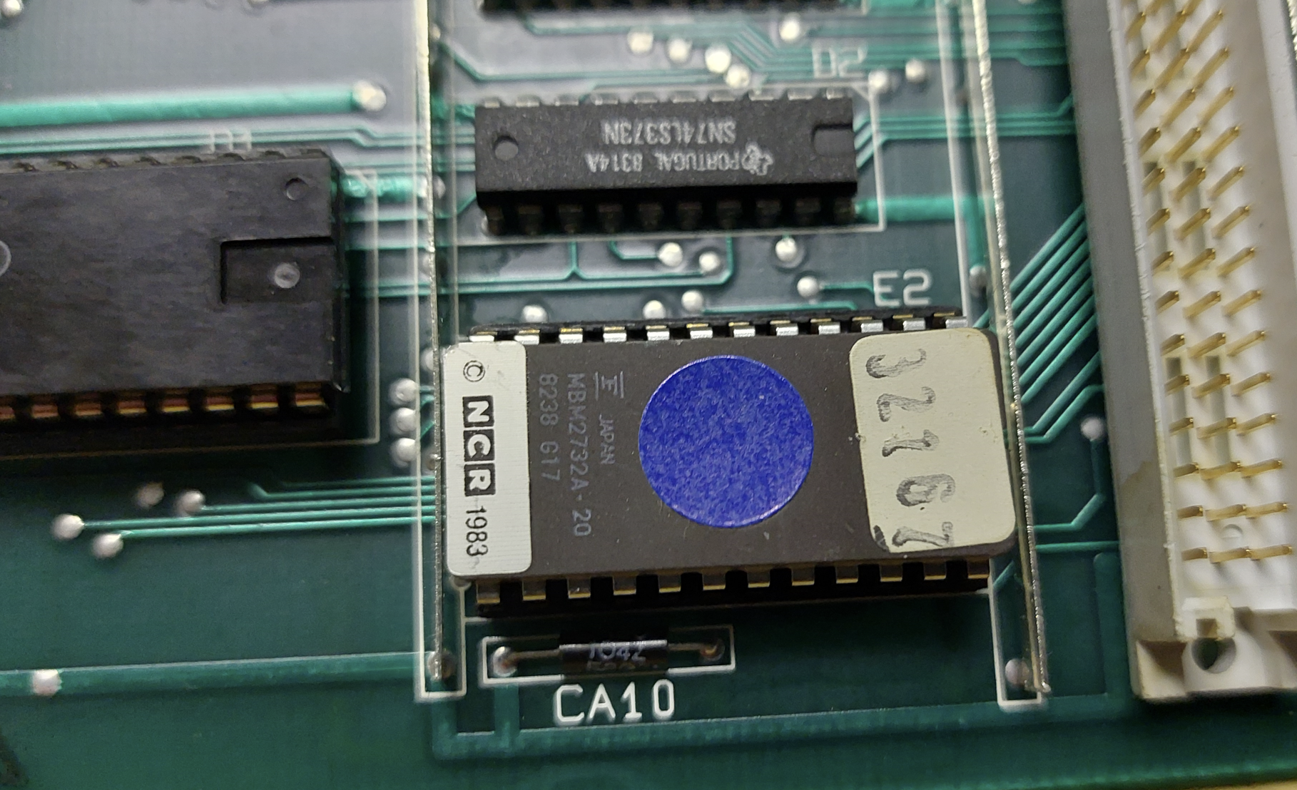
I dumped the following ROMS while I had the machine dismantled
Main Board: D14 D2764
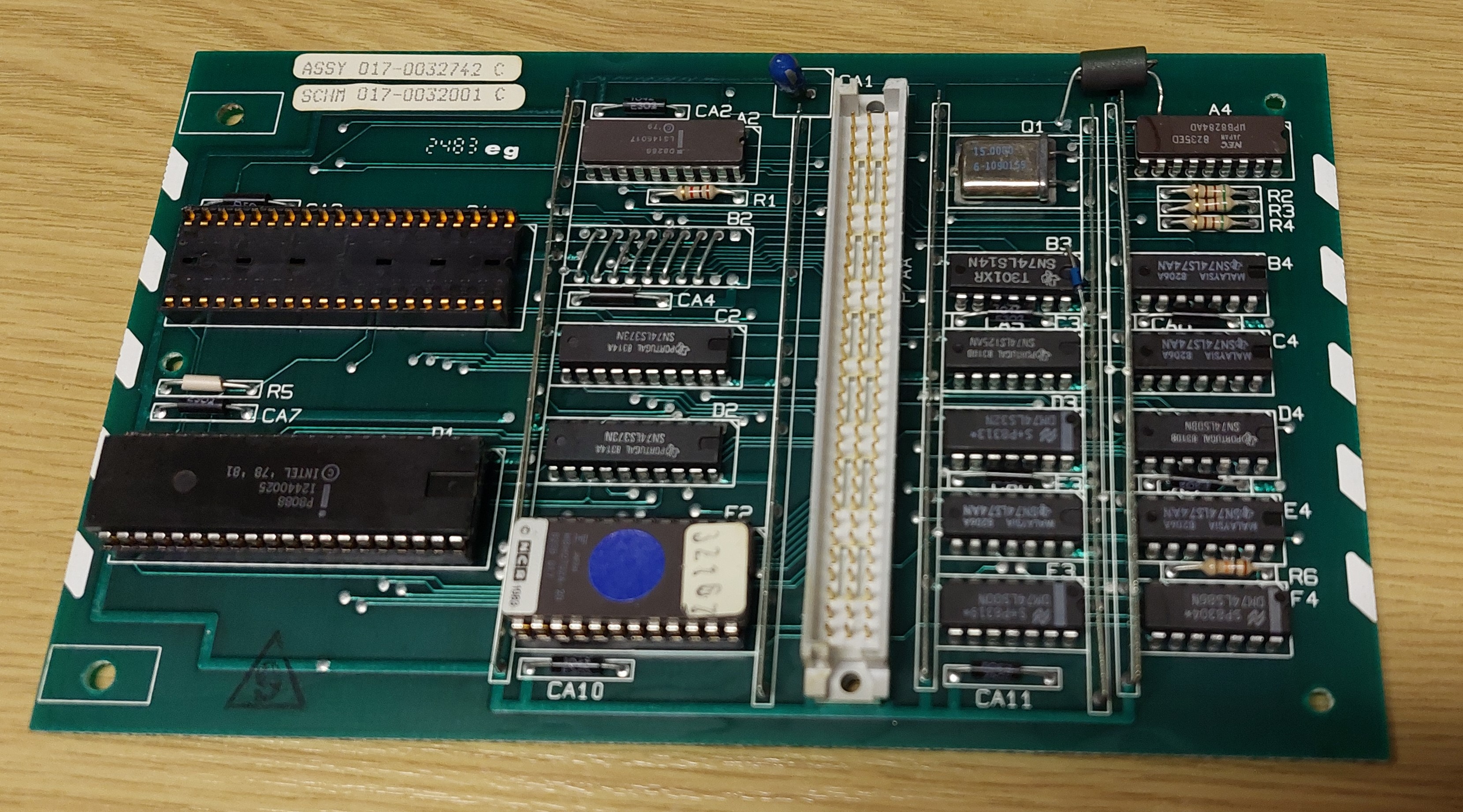
8088 Expansion Board: E2 MBM2732A
Other resources online
- 🌐 Old Computers Rechner NCR DMV
- Manuals
- Software
- Photos
- Schematics
Additional Photos